
Page 104 - Vehicle Products Catalogue EN 012019
P. 104
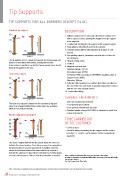
Tip Supports

TIP SUPPORTS FOR ALL BARRIERS (EXCEPT BL4X)

Standard tip support650 - 1000                                            DESCRIPTION

 5650 - 1000                                                              1.	Bollard composed of 2 telescopic elements in tubular steel
                     2                                                       with a square section, allowing the height of the tip support
650 - 1000                                                                   to be adjusted
 1
                                                                          2.	Locking bolt for fixing the tip support at the required height
 34                                                                       3.	Base plate for attaching the unit to the ground
                                                                          4.	Concrete base plate for attaching the tip support to soft
                                                          275
                                                                             ground
The tip support acts as a guide and support for the long range arm        5.	Arm guiding support, preventing any attempts to force the
barriers or those fitted with options, making them heavier.
It also makes it possible to protect the barrier geared motor should         arm sideways
pressure be applied to the arm.                                           6.	Hinged folding stirrup
                                                                          7.	Padlock
Locked tip support                                                        8.	Magnetic arm lock unit

 76                                                                          Nominal voltage: 24V DC
                          2                                                  Absorbed power: 20.5W
                                                                             Protection: IP65, according to DIN40050, insulation class E
 5                                                                           Support force: 200kg
 1                                                                           Diameter: 100mm
                                                                          9.	Adhesion disk mounted on a rubber silent block and fixed to
 34                                                                          the end of the arm and inside it, guaranteeing perfect contact
                                                                             with the arm lock support surface
                                                           275            10.	Connection wiring

This type of tip support is identical to the standard tip support         SURFACE TREATMENTS
above, but a hinged folding stirrup, held in place by a padlock,
allows it to be bolted manually.                                            Anti-rust cataphoresis treatment
                                                                          772-component epoxy primer
Electro-magnetic tip support                                              772-component polyurethane top coat
                                                                          77Standard shade: orange RAL 2000, or adapted to match the
 5
 89                                                                         colour of the barrier
 1
 2                                                                        TO BE CARRIED OUT
 3 10 4                                                                   BY THE CUSTOMER

                                                      275                 77Concrete base
                                                                          77Electrical wiring connecting the tip support and the barrier

                                                                            housing: 2 x 1.5mm² + earth (only for electro-magnetic tip
                                                                            supports)

The electro-magnet built into the tip support allows the arm to be        Note : Adding an adhesion disk to the arm increases the weight.
bolted in the closed position. Since the arm cannot be manipulated        In order to guarantee an equivalent lifting drive, the range of an arm fitted with
by hand security of access is guaranteed. In addition, since the          this option is limited.
electrical connection between the barrier and the tip support is          See the Usage Limits Rate table.
buried in the ground, it is impossible to interrupt the electrical power
arm lock unit because no wiring is directly accessible to the public.

With a constant view of adopting the latest technological developments, Automatic Systems reserves the right to amend the information above, at any time.

Products Catalogue | Vehicle | 104