
Page 93 - Vehicle Products Catalogue EN 012019
P. 93
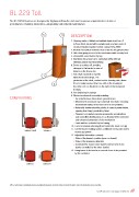
BL 229 Toll

The BL 229 Toll barriers are designed for highway toll booths and meet numerous requirements in terms of
performance, reliability, robustness, adaptability and reduced maintenance.

                                       54                 DESCRIPTION

                                       1                  1.	Housing made of folded and welded sheet steel, from 2
                                                  3          to 6mm thick, protected by cataphoresis and two coats of
                                                             structured paint (standard colour: orange RAL 2000)
CONVENTIONS
                                                          2.	Internal mechanical elements treated by electro-galvanisation
                  Door                                    3.	Side door giving access to the mechanism with security lock
                                                    Door  4.	Removable cover locked by key
                                                          5.	Aluminium tube boom arm, varnished white with red
Solution 1 (std)                       Solution 2
                                                             reflecting stripes and end-sealing
Door                                                      6.	Boom arm swing-off, avoiding
                                 Door
                                                             damage to the barrier in case of
                                                             impact on the boom arm
                                                          7.	Arm shaft mounted on two life-
                                                             lubricated ball bearings. The
                                                             protrusion of the shaft, centred on the housing side, allows
                                                             it to be easily reversed from one side of the housing to
                                                             the other: arm on the left or on the right of the framework
                                                             housing
                                                          8.	Arm balancing by springs
                                                          9.	Electro-mechanical assembly including:
                                                             77An asynchronous three-phase geared motor
                                                             77Movement transmission by crankshaft-rod device ensuring

                                                                mechanical locking of the boom arm in end positions
                                                             77Automatic barrier unlocking device in case of power failure,

                                                                opening then being possible by hand
                                                             77Frequency converter ensuring progressive accelerations

                                                                and controlled decelerations, for a vibration-free movement
                                                                and enhanced protection of the mechanism
                                                             77Limit switches activated by leaf spring
                                                          10.	Lever for manual unlocking (if not automatic mode set up)
                                                          11.	Control board enabling various additional commands and/or
                                                               accessory options
                                                          12.	Adjustable information contacts:
                                                             77State of the barrier’s position (open or closed)
                                                             77State of the presence detectors
                                                             77Command for master-slave barriers (movement of one
                                                                barrier controlled by the other barrier)
                                                          13.	Fixing frame to be fixed in a concrete base to be provided
                                                               by the customer

Solution 3                             Solution 4

With a constant view of adopting the latest technological developments, Automatic Systems reserves the right to amend the information above, at any time.

                                                                                                                 93 | Products Catalogue | Vehicle